


How do you select the model and parameters of NTC thermistors?
What are NTC thermistors?
NTC thermistors are high-performance resistor devices whose resistance values change significantly with temperature. This characteristic makes NTC thermistors widely used in temperature measurement, compensation, and control. This article will provide a detailed guide on selecting the model and parameters of NTC thermistors based on their specifications.
NTC Negative Temperature Coefficient Principle
NTC thermistors have a Negative Temperature Coefficient (NTC). They are primarily made from metal oxides such as manganese, cobalt, nickel, and copper and are manufactured using ceramic processes. NTC thermistors can be customized regarding product parameters and form factors to meet various application needs. They are known for their high reliability, stability, and precision, making them suitable for multiple applications.
NTC Thermistor Models and Parameters
The models and parameters of NTC thermistors can vary depending on the manufacturer‘s technology. Below is an introduction to some common NTC thermistor models and their selection parameters.
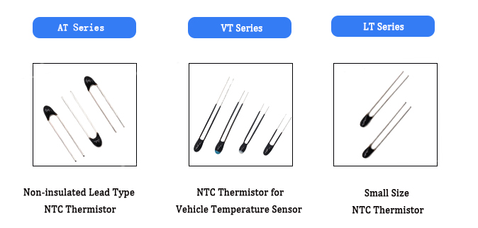
Non-insulated lead type NTC thermistors have good thermal cycling resistance and stability, making them suitable for manufacturing small household appliances, automobiles, computer motherboards, chargers, air conditioning equipment, etc.
· Operating Temperature Range: -50°C to +125°C· High Precision: Available with tolerances of ±1%, ±2%, ±3%
· Good Thermal Cycling Resistance
· High Stability
GT
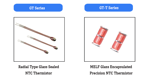
The GT series NTC thermistors are glass-encapsulated. Due to their special properties, they can be used stably in harsh environments such as high temperatures and high humidity for a long time. They are small in size, light in weight, and have a robust structure, making them widely used in various fields such as steam ovens, e-cigarettes, and automotive drive motors.
· Thermal Time Constant: Maximum 2.5 seconds in oil bath.· Dissipation Factor: Approximately 0.5 mW/°C in still air.
· Rated Power: Maximum 35 mW in still air.
· Insulation Resistance: 10 MΩ between lead and glass.
· Operating Temperature Range: -40°C to 500°C.
Technical Parameters of NTC Thermistors
- Zero-Power Resistance RT
At a specific temperature, the resistance value measured using a power level that causes a negligible change in resistance compared to the total measurement error is defined as the zero-power resistance RT.
- Zero-Power Resistance at 25°C R25
This refers to the zero-power resistance value measured at 25°C. Unless otherwise specified, this value is the thermistor‘s design resistance value and also its nominal resistance value.
- B Value (K)
The B value is the thermosensitivity index of an NTC thermistor, reflecting the change in resistance with temperature. It is defined as the ratio of the difference in the natural logarithms of the zero-power resistance values at two temperatures to the difference in the reciprocals of those temperatures. The specific formula is:
B=(T11−T21)ln(RT2RT1)
Where:
RT1 is the zero-power resistance at temperature T1.
RT2 is the zero-power resistance at temperature T2.
T1=273.15+T1∘C, T2=273.15+T2∘C.
Unless otherwise specified, the B value is calculated using the zero-power resistance values at 25°C (298.15K) and 50°C (323.15K). It is important to note that the B value is not a strict constant within the thermistor‘s operating temperature range.
- Dissipation Factor δ
The dissipation factor δ is a crucial thermal characteristic parameter that indicates the relationship between the rate of power dissipation and the corresponding temperature change under ambient temperature conditions. It is defined as:
δ=ΔTΔP(mW/℃)
The dissipation factor δ represents the power required to raise the temperature of the thermistor body by 1°C. Within the operating temperature range of the thermistor, δ varies with ambient temperature. This means that the thermal dissipation characteristics of the thermistor may differ at different operating temperatures. Therefore, engineers need to consider the impact of this variation in design and application.
- Thermal Time Constant τ
The thermal time constant τ is another key thermal characteristic parameter that describes the response speed of the thermistor to temperature changes. It is defined as the time required for the thermistor‘s temperature to change by 63.2% of the difference between the initial and final temperatures under zero-power conditions. It is given by:
τ=δC
Where:
C is the thermal capacity of the thermistor.
δ is the dissipation factor.
- Rated Power Pr
The rated power Pr is calculated using the following formula:
Pr=δ×(Tmax−25∘C)
- Resistance-Temperature Characteristic
The resistance of a thermistor changes with temperature according to the following relationship:
R=R1×eB(T1−T11)
Where:
R is the resistance at absolute temperature T (in Kelvin).
R1 is the resistance at absolute temperature T1 (in Kelvin).
B is the B constant.
T=T(∘C)+273.15.
This formula describes how a thermistor‘s resistance changes with temperature and is fundamental to temperature measurement and control applications.
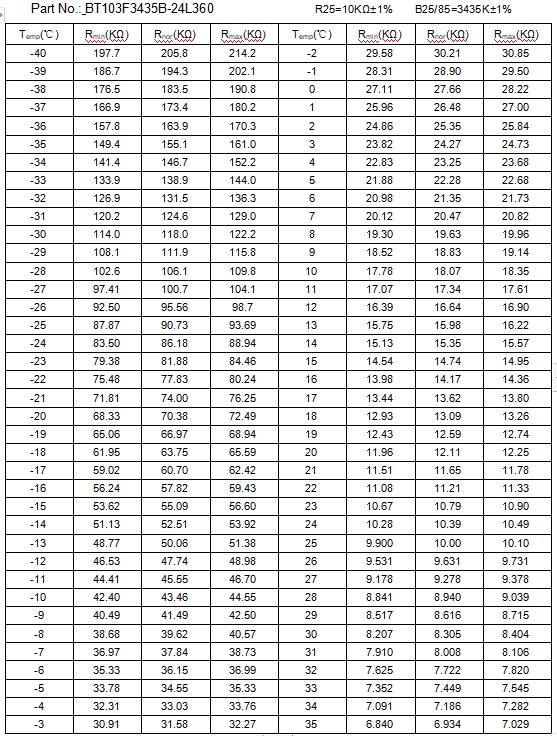
R-T Table
The R-T table for NTC thermistors is essential data that electronic engineers need when designing circuits. The table is calculated using the above formula, and the temperature intervals can be freely set. Given the precision of NTC temperature detection, the temperature interval is typically set to 1°C. For example, the following table:


 Email
Email EXSENSE Eva

